MAE5190
Class Repository for Spring 2026 MAE5190
Project maintained by hw846 Hosted on GitHub Pages — Theme by mattgraham
Lab 12 Overview:
In this lab, I learned how to “flex my control mmuscles” and turn my car into an Inverted Pendulum on a Moving Cart problem! Using the Orientation PID from Lab 6 and the open-ended testing framework from Lab 8 I was able to successfully drive my car on its back wheels for an extended period of time.
````Final Wordcount: 950```
Considering Options for Control
When I first started this lab, I wanted to consolidate my design choices as much as possible in order to have a consolidated prototyping pipeline that could streamline my path towards a solution. Given that my Lab 8 was a Drift rather than a Flip, I wanted to keep my system simple and start it from an upward position. Beyond this decision, for my pipeline I drafted this testing direction which worked well for this lab: 1. Test adding weights to the Car 2. Comparing Lab 3's complimentary filter to Lab 6's DMP for Roll/Pitch in order to streamline processing 3. Test hand tuning PID values in both prior systems Shown in the sections below are my prototyping steps to test these steps:
Adding Weights to Car
Looking at this system as an inverted pendulum problem, I knew I wanted to keep my center of mass as low as possible. This would reduce the moment load on my car from gravity as it stabilizes. From rudimentary testing (i.e. balancing a car on a ruler to see where my COM lies) I noted that my car was very well balanced and had its COM at the relative center. Thus, to drop it lower I took a test tube filled with metal nuts and attempted sticking it onto my car as shown:
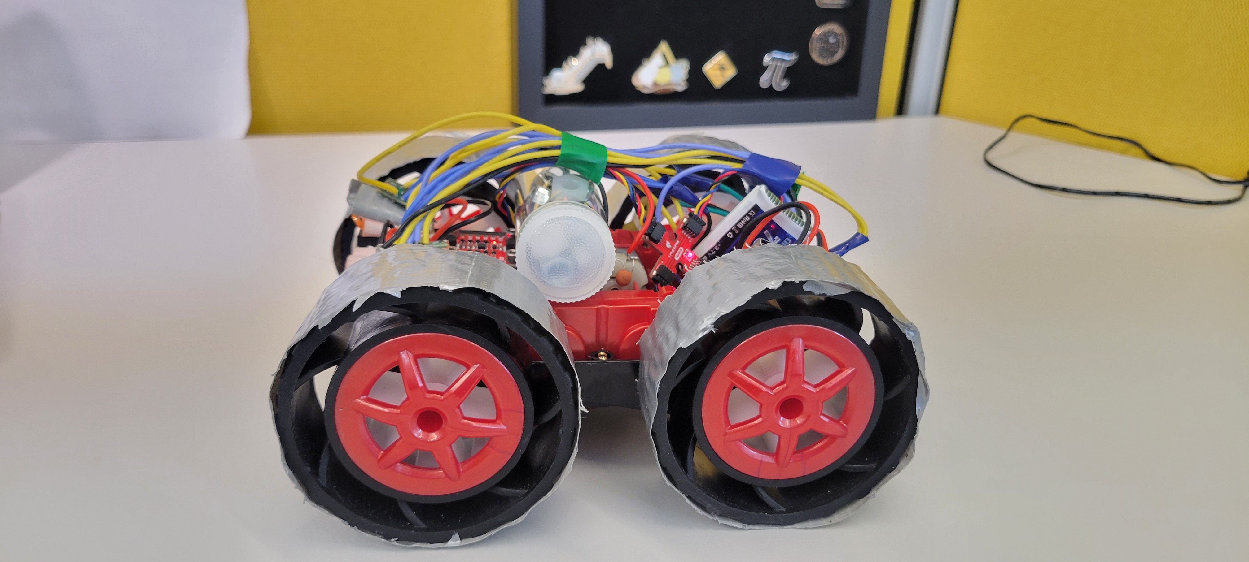
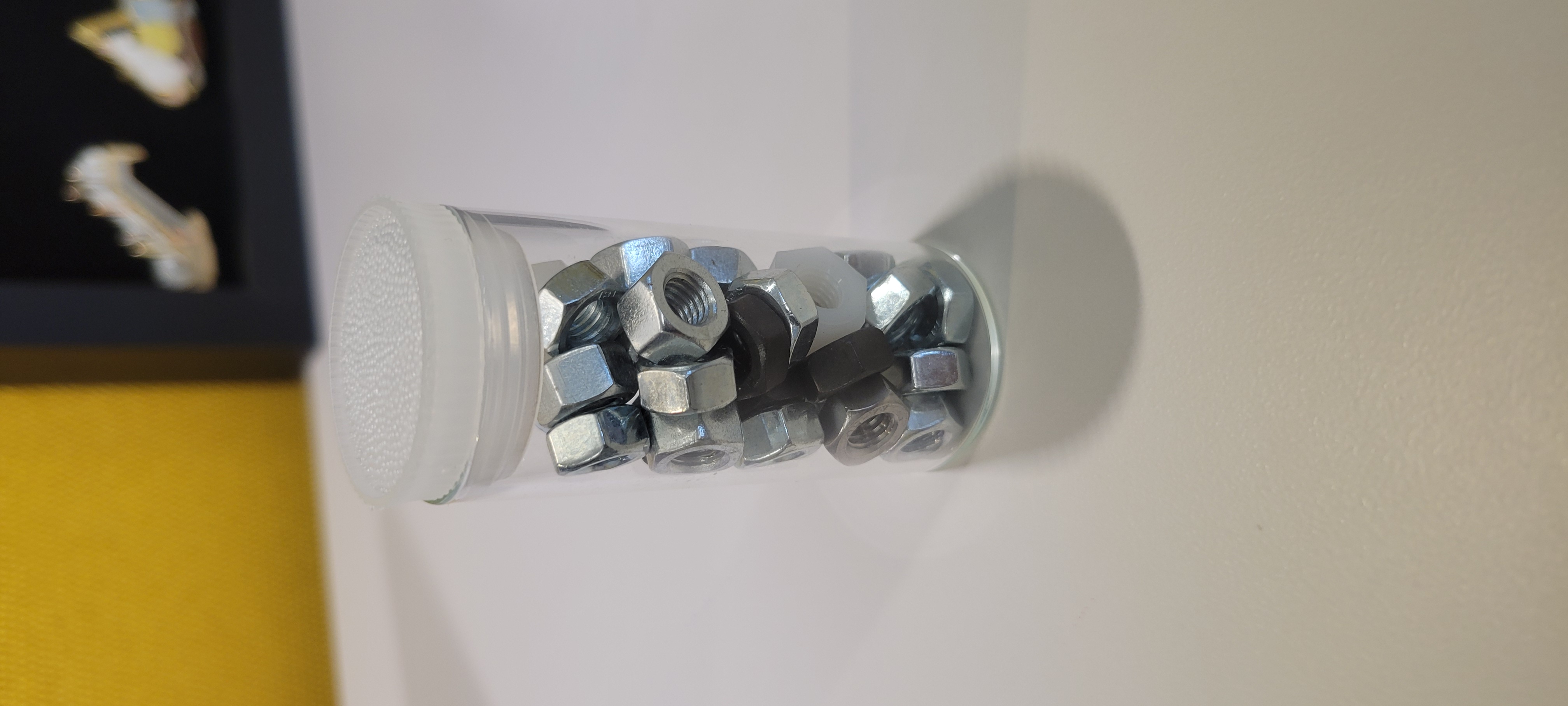
The issue with this was mostly in its unevenness as adhering it to one side or the other would skew the COM to that side. Thus, I took the original battery holder for the car as a storage due to its more central location & large capacity. This, as tested/shown in later sections, helped me a lot to balance my car.
Complimentary Filter vs. DMP
Reusing my codebase from Lab 3 and Lab 8 for roll outputs I decided to benchmark how noisy each technique was (as I knew my final system needed to be very smooth in order to facilitate smooth micro movements).
// Complimentary
  acc_roll = (atan2(myICM.agmt.acc.axes.x, myICM.agmt.acc.axes.z))*(180/M_PI);
  LPF_roll[1] = alpha*acc_roll + (1-alpha)*LPF_roll[0];
  LPF_pitch[1] = alpha*acc_pitch + (1-alpha)*LPF_pitch[0]; */

  gyr_roll[1] = gyr_roll[1] + myICM.agmt.gyr.axes.y*(-0.00011);

  com_roll[1] = (com_roll[1] + gyr_roll[1])*(1-beta)+LPF_roll[1]*beta;

  com_roll_tracker[time_count] = com_roll[1];
  com_roll_tracker[time_count-1] = (com_roll[0] + gyr_roll[0])*(1-beta)+LPF_roll[1]*beta;
// DMP
if ((myICM.status == ICM_20948_Stat_Ok) || (myICM.status == ICM_20948_Stat_FIFOMoreDataAvail) && (dmp_data.header & DMP_header_bitmap_Quat6) > 0) {
          updatePWMTurn = true;
          q1 = ((double)dmp_data.Quat6.Data.Q1) / 1073741824.0;
          q2 = ((double)dmp_data.Quat6.Data.Q2) / 1073741824.0;
          q3 = ((double)dmp_data.Quat6.Data.Q3) / 1073741824.0;

          qw = sqrt(1.0 - ((q1 * q1) + (q2 * q2) + (q3 * q3)));;
          qx = q2;
          qy = q1;
          qz = -q3;

          double t0 = +2.0 * (qw * qx + qy * qz);
          double t1 = +1.0 - 2.0 * (qx * qx + qy * qy);
          double roll = atan2(t0, t1) * 180.0 / PI;

          dmp_roll[1] =  atan2(t0, t1) * 180.0 / PI;
          LPF_roll_tracker[time_count] = 0.3*dmp_roll[1] + (1-0.3)*dmp_roll[0];
      }
  else{
    LPF_roll_tracker[time_count] = LPF_roll_tracker[time_count-1];
  }
  dmp_roll[0] = dmp_roll[1];
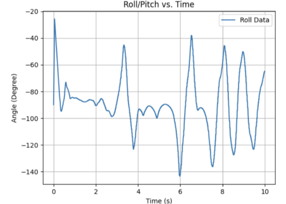
Using the same code framework, and a basic kP value of 1.0 to drive it, I had these outputs from my system for both complimentary and 5Hz DMP:
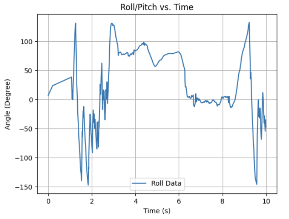
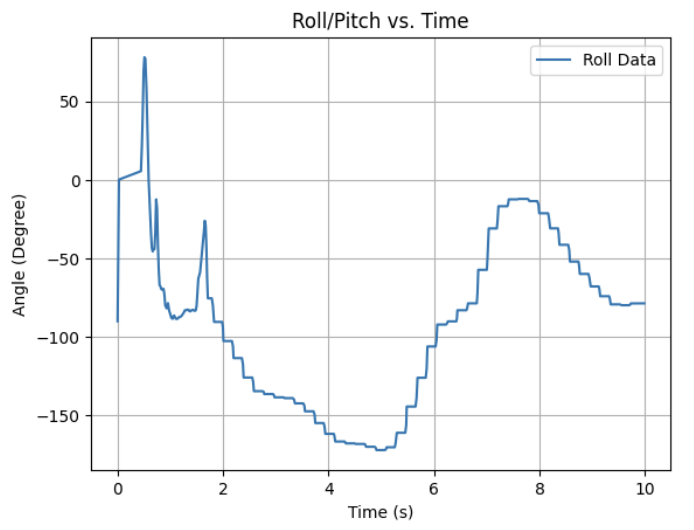
As seen, the DMP was much less noisy due to the quaternion and sensor fusion approach comparatively but ran at a much lower frequency (set low from Lab 11 to simplify the system). After pulling it up, I had this smooth output when running:
With a now smooth output, I moved on towards tuning my PID values.
Hand Tuning PID
For this section, I used the given code for my PID implementation (as pulled from Lab 11)
while (central.connected() && ((millis() - start_time) < (unsigned long)max_samples && time_count < max_samples) )
  {

    GET_IMU_TOF_DATA();
    if (updatePWMTurn)
    {
      POS_dt = (time_tracker[time_count] - time_tracker[time_count-1])*0.001;
      POS_error = LPF_roll_tracker[time_count] - POS_goal;

      POS_P = Kp * POS_error;

      if (abs(PWM) < 255) { POS_I_INT = POS_I_INT + POS_error*POS_dt; }

      POS_I = Ki * POS_I_INT;
      POS_I = constrain(POS_I, -255, 255);
      POS_D = Kd * ((POS_error - prev_error) / POS_dt);
      POS_D = constrain(POS_D, -255, 255);
      PWM = constrain(PWM, -255, 255);

      //Deadband and Directional Code
    }
  }
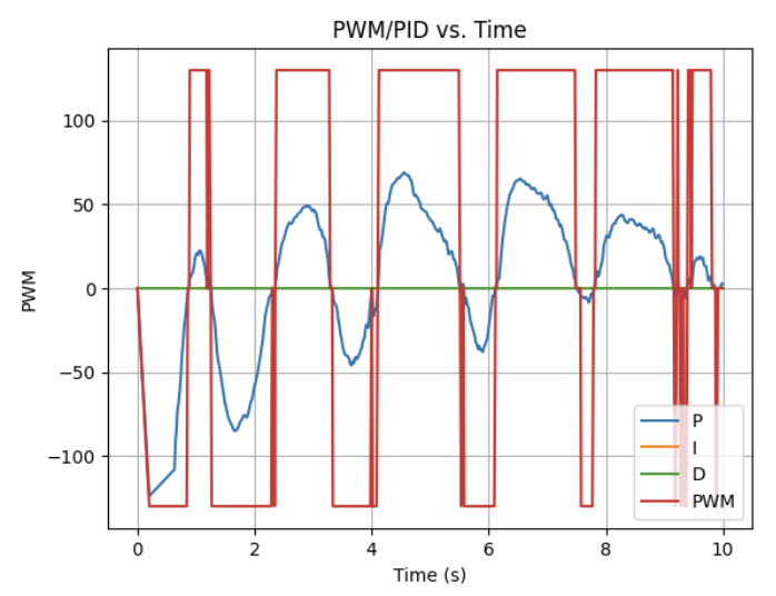
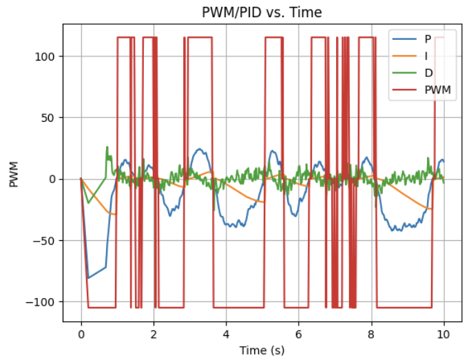
Compared to my previous attempts at PID, because this version of my system had much less friction to overcome (i.e. less contact with the ground) I lowered my deadband considerably to 25PWM in order to prevent anything close to Bang-Bang creating very oscillatory movements. Had I kept the same deadband, my PWM values became highly unstable (even with higher PID values) even with higher kD values to compensate:
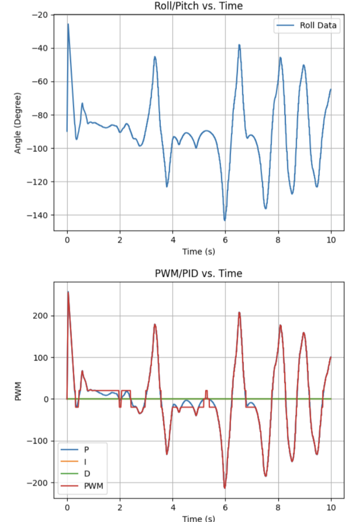
With this set, I began tuning my PID values. To first tune my system, I turned my kP value as high as possible till it reached oscillatory motions. At Kp=10.0 I reached this attempt below:
After this, I began testing out my kD values to account for the future error in my system (i.e. prevent overshoot sending my robot crashing down). I originally set my Kd=3.0 which was inhernetly too high and led to very jagged data/motions as shown below:
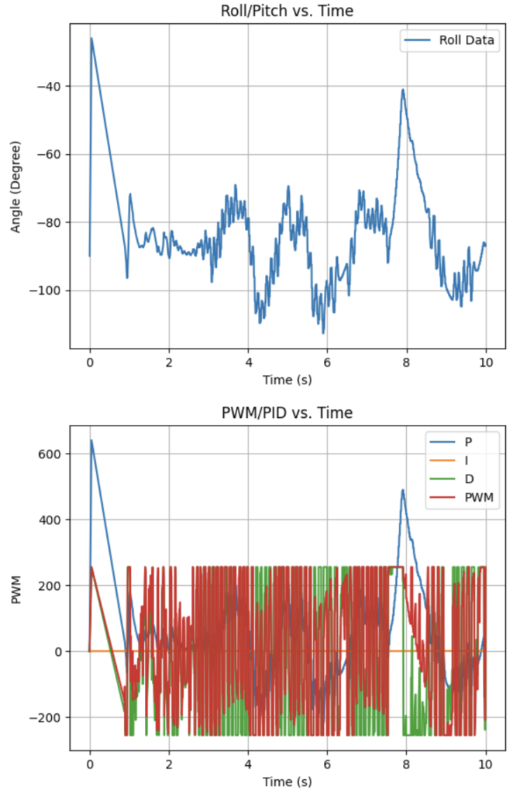
After some stepping down, I eventually settled on a kD vaue of 0.25 for my system and had this semi-successful attempt:
With this attempt now successful in a small scale in my lab, I moved it to the hallway outside my lab to facillitate my final testing.
Results
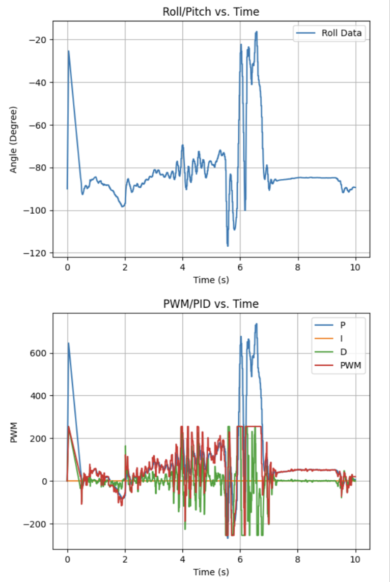
With everything set up and working, I had the following test runs and outputs (with the most successful and least dorky being first):
And then some more successful attempts that were just fun/funny (“I’m Johnny Knoxsville…”):
Becasuse my system had no kI value and an “underpowered” kP, it led to this large amount of forward movement to enable stability (essentially driving forward rapidly to keep it in a faux-free fall). If I were to reimplement this, I would try to have a more fine tuned kP and kI to account for this and keep it stable without this driving motion. Despite this, my system could run for a long period of time without being pushed into instability until it hit some form of obstacle in the environment.
Discussion
In this lab, I learned how to apply everything I learned thus far in one final amazing demo. Although the task was difficult and required a more intense prototyping framework compared to previous labs, the end result was nevertheless impressive and super fun to work on!
I’d like to end this saying thank you to the Teaching Team and Dr. Helbling for a great semester! While tough and time-intensive, this class has been a blast in terms of both content and labs. It was very fun to physically build up my robot and do so many cool things I learned only theoretically in my classes. Thank you again for a fun semester, and hope everyone has a great Summer :]